A number of people have responded positively to the project video I published last summer on converting my Grizzly G0704 milling machine to CNC, and one of the biggest questions has to do with parts sourcing and total costs, so I thought I would do a quick breakdown. Any links in this post are affiliate links so if you use them, I get a few pennies to keep breaking end mills with! I’ll share the major components I used, any parts that are specifically referenced ONLY WITHIN Hoss’s plans, I will let you buy his plans from him to discover them, but will share a basic cost breakdown. (more…)
I was wary at first, but I’ve come to be a huge fan of 3d printing. It goes hand in hand with CAD modeling, it can be used to test out designs or manufacture small widgets for the shop (or anything), and can be fun for making toys and other novelties. Up to now I’ve been printing on an Anet A8 printer; the infamous $165 eBay special that you build out of precut acrylic plates. To be honest it works well enough for what it is, minor adjustments are a near-constant necessity, and I’ve had my share of failed prints.
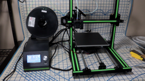
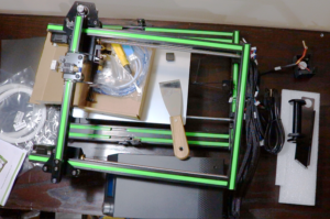
I was recently approached by a Chinese distributor of Anet printers, Gearbest.com, about the new offering from Anet, the E10. The E10 boasts a larger build area, an all-aluminum construction, a self contained controller box, and a slightly larger build area, amongst other upgrades. Gearbest offered to send me a machine in exchange for a review, so for transparency’s sake, you should know I did not pay for this machine, however, I was not given monetary compensation to review this machine. Once an agreement was met they sent me the machine so I could evaluate it.
The machine shipped directly from china and came packed well and secure. In addition to the core components of the machine, you will also receive:
2 10m lengths of PLA (mine was white, I make no assumptions what color they will send out with others)
a set of Allen wrenches
a phillips/flat head screwdriver
a USB microSD card adaptor
a MicroSD Card (This has comprehensive build instructions as well as a lot of other data on it, so be aware of that)
a USB cable
a sheet of adhesive print bed material made by 3M (not sure what, specifically, this product is)
a baggie full of spare T Nuts sized to fit the aluminum extrusions
a spare extruder Nozzle
a printed assembly pamphlet (very helpful but not as comprehensive as the instructions on the SD card)
Compared to the very-involved assembly of the A8, the E10 goes together very swiftly. Essentially, all you need to do is attach the upper frame to the lower frame, attach the hot end to the X Axis slider, and plug in all of the electrical components. As far as actual assembly goes, that’s it. A nimble-fingered person could likely do it in about 10 minutes, maybe even less. Setting up a camera between each process drug the whole operation out to closer to 20 minutes for me. Still, this is a massive difference from the 6-ish hours the A8 took me to assemble.
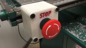
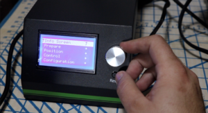
With the machine assembled, it was time to turn it on. The very first thing I noticed was how loud the controller box and all the fans are. We’re talking Gaming PC loud here. My initial optimistic thought was that the cooling of the controller box needed to be powerful because of the complexity of the controller. There are two interface inputs for the controller box; the first being a clickable wheel which you use for 100% of navigating through menus and selecting options, settings, etc. The wheel is novel, and the concept is solid, however, mechanically, the wheel can be difficult to use as it takes two or three “positions” of turning before it actually starts registering on screen. This can be very frustrating and the closest thing I can compare it to is like dealing with excessive backlash on the drive screw of a machine. The second interface on the controller box is a reset button, which is exactly that. Hit the button, and the machine off-and-on-again’s itself. This is a super convenient E-Stop for when your print starts failing, however, it is also frustratingly close to the dial wheel, causing accidental resets (oh boy ask me how I discovered this!) The controller box’s software is similar to the A8’s, it offers more control in some ways, and less control in others. Things I like about the A8’s controller screen are a readout of the Z height, as far as where the machine thinks it is, which is handy in dialing things in and solving issues, as well as an easy way to switch between finely stepping the motors or rapidly traversing them. The E10’s controller doesn’t feature these, it offers different distance/speeds to move the motors, but only certain speeds for certain axes, which is odd and makes things slow.
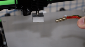
Running a basic preheat procedure for PLA led me to discover the first issue; the nozzle just wouldn’t come up to temp. The table, on the other hand, came up to temp very quickly, much faster than the table of the A8. In diagnosing the nozzle I quickly discovered that the heating element’s thermocouple is too short to properly seat inside the heating block of the nozzle, and causes it to misread a much lower temperature. It was very frustrating to get the thermocouple into position; the wire bundle that holds it has to be pinched through a tight slot in the cover box for the tight end; this puts strain on its wire and can easily undo any careful adjustments you’ve made to get the thermocouple to its home. Trying to get the thermocouple into where it belongs to the point it would give me a (relatively) accurate temperature reading added another hour to the setup time. I’m actually a little worried that I’m still not getting an accurate temperature reading, and that my nozzle is far too hot.
After that amount of adjusting and fiddling just to get the machine to preheat, I immediately came upon the next problem; the filament wouldn’t feed. Once again chasing the problem, adjusting, fiddling, etc., added about an hour to discover that the nozzle on the machine was clogged as it came to me. Thankfully the machine comes with another nozzle and I was able to finally change it out to one that would allow me to finally print.
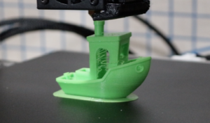
The first print was of the ubiquitous “Benchy.” Benchy is a little cartoonish boat with a number of 3d features on it, and the 3D printing community has adopted it as an unofficial first test print for any new 3d printer, a “benchmark.” Benchy came out just fine using PLA I sourced from a local computer store. The windows and some of the edges had little “hairs” floating in the gaps and off the sides; I presume I either had my nozzle set too hot or the nozzle is hotter than the machine thinks it is. However, I consider it to be a very successful print and a great example of what this machine is capable of!
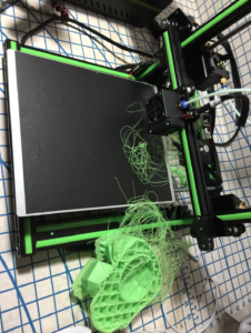
I next tried to print a large “Bulbasaur” Vase, a file I found on Thingiverse. The print started off just fine and I actually let it print overnight– the first and only time I ever did that with this printer. We woke up the next morning to an absolute mess and an obviously failed print. After reviewing the time lapse footage, somewhere during the print, the entire Z axis started moving down instead of up. Spoiler alert- this happens a lot more. I double checked all my settings and adjustments in both the machine and in Cura, my print slicing program. I found no direct culprit, but decided to keep trying prints.
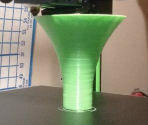
I modeled up a trumpet-style cone in Fusion 360 based off a fun idea I had. Towards the end of the print, the same issue occurred and I stopped the print once I realized the Z Axis had reversed itself and was going back down. Once again frustrating and confusing. The print itself also seemed to have more layer lines than the Benchy model, reminding me of some of the lower quality prints I’d come up with on the A8 whenever it wasn’t well adjusted.
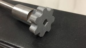
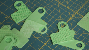
Without being able to diagnose an actual culprit for why the Z Axis just decided to switch directions at a random level, I pushed on and started printing pieces out of a future project, which I happened to have modeled up in Fusion 360. These are intended to be CNC Machined out of cold rolled steel, but I figured it’d be fun to print them out before hand. I started by printing the base piece of the part which is a relatively simple, boxy geometry. Amazingly, it printed without issue. There were a couple of odd spots where the flow seemed to change, like little swollen patches around the side, but other than that the part came out looking fine and being accurate to its necessary dimensions.
With this success I went to print the next pieces of this project, two uprights, of similar size and geometric style. The printer just wouldn’t print them. Several non-starts or failures at the first level. I tried at least half a dozen times to print these, each time of course making sure my bed was properly level and my nozzle height was properly set. I tried different g code files, different settings in Cura, different orientations, it’s as if the printer would just throw a tantrum trying to print this specific shape. I’m honestly still entirely befuddled. I was even able to get successful prints of other items in between these prints, so it’s not like there was some wild maladjustment on the machine itself. Unfortunately, frustrating.
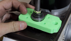
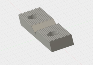
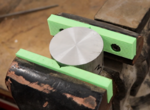
Going with a different direction, I wanted to try an experiment I’ve thought of in the past of 3d printing a set of soft jaws for a bench vise– I still think this would be a viable means for making soft jaws and even specifically shaped jaws, say for the CNC Mill. I took dimensions of the existing jaws and plugged those into a sketch in Fusion 360 and started designing the parts. I added in a V Groove for holding round objects to the center of the Jaws and also modeled in some triangular “teeth” as an interesting design element. These features were mostly for fun and as an example of concept, instead of being based on any actual design. Once again in a surprising manner, the part made it all the way through the printing process, and actually mounted to the vise! If one were doing this sort of operation, I would recommend 100% infill, as it is I used 15% and expect the jaws to be appropriately weak. They did, amazingly, hold into a 2.5″ piece of aluminum round rather well, stiff enough to do some light filing into the top, so even though they were printed as an example, they are actually useful. Hitting the aluminum with a hammer, however, was (obviously) enough to unseat the part with minor damage to the contact points in the vise jaws. These jaws printed, but didn’t print perfectly; there were hairline gaps all amongst the sides and a few layer variations, small but noticeable defects.
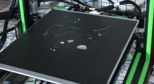
After about a dozen prints, the 3M Print bed covering shows a good amount of wear. I give it credit for how well PLA sticks to it, I’ve had zero issues with print bed adhesion, which is actually nice because that’s the biggest issue I run into with the A8. The material sticks so well, however, that it tends to leave little bits of itself to the bottom of prints. This can be a little frustrating if you aren’t wanting a little black spot on the bottom of whatever you’re printing, plus it creates a damaged spot on the bed. I’m not sure how easy it’s going to be to change out, it’s stuck down fairly well and it seems like the plate underneath will need a thorough cleaning to get all of the residue off.
So, all in all, my overall opinion of this machine is, unfortunately, not great. For it’s price point (around $300US) it bears a very competitive set of features; the aluminum frame, the controller box, and the large print area. I had very high hopes for this machine to at least be decent, I was excited to have it to expand my 3d printing capabilities. I really, really wanted to be able to give you a review that said this machine was the next step up from an A8 and a great upgrade in machine for only a small upgrade in price. Sadly, I have not had a very reliable time with it. I’ve had more fails and mis-starts than completed prints with this machine, by a large order. There are some Quality Control issues that are very small things but make a huge difference, like the thermocouple and extruder nozzles, two tiny details that required quite a bit of buggering before the machine was even ready to make its first print. I’m honestly thinking that something in the controller software or the firmware is flawed, causing the huge issue with the Z axis wanting to reverse randomly mid print. As stated before I’ve explored every possible setting, option, and adjustment in preventing it, to no avail. As it is, I’ve had significantly more success with the cheap little A8 printer over the last several months (I bought the A8, by the way, knowing absolutely zilch about 3d printing at the time so I’d dare say it scores double points for being remarkably idiot-friendly) than I have in the past few weeks going round and round with this E10. I sincerely hope whatever issues with this machine can be resolved, and if I figure out the source of mine, I will happily give an update.
If you are interested in purchasing this machine for yourself, here is a referrer link to it http://www.gearbest.com/3d-printers-3d-printer-kits/pp_664901.html?lkid=11126217
I do get a small percentage of the sale if you purchase it through that link. The code ANET10 will get you a price of 279.99 with a spool of filament.
This is one of the last projects from my “old” shop; a bit of a long term one based on an idea I’ve always had.
Lever action rifles have always been fascinating to me. They offer a unique compact and rugged versatility, and a wide range of utility. I’ve wanted to take one and modernize it, but part of the dilemma is the destructive aspect of taking a gun that’s designed to be a useful work of art; gorgeous carved wood and polished metal, and cutting and refinishing on it.
Some time back my wife bought a classic Marlin 336 rifle. Relax, I didn’t do anything to it. This became her “mainstay” hunting rifle for when we get the opportunity to hunt deer. Before she got that rifle, I’d never had experience with the .30-30 round and it’s wide variety of loadings and offerings. While I’ve used a .308 Remington 700 as my hunting rifle for a number of years, I really became infatuated with her rifle. It’s lighter weight, has a more “lean” form factor, easier to load and unload, and of course is a little faster with a followup shot (not that I would ever need one, right? ;))
This gave me the idea to find a Marlin 336 that I wouldn’t feel bad about doing this gunsmithing work on. Aside from just being a fan of Marlin rifles in general, I particularly liked the 336 as a candidate for this project as it featured a loading gate (some lever action rifles based on older designs do not have the side loading gate) as well as a solid top receiver, ideal for mounting optics (Winchester 94s, for example, are top ejection and therefore not ideal for optics usage.) Additionally, a feature of the Marlin rifles that is bad for customers but slightly more ideal for tinkerers; Marlin went through (some say still is going through) a period of lower production standards and decreased quality control after they were purchased by the Freedom group. The firearms put out by the company after this change in ownership showed a distinct and tangible lack of finish detail and overall quality that the older rifles boast. This means that the one you buy off the shelf is not going to have the same beautiful wood and metal and super slick action that, say, my wife’s 70’s model has. This, and almost entirely this, are what ease my conscience over completely reworking and refinishing a rifle; it’s done without taking an otherwise beautiful gun out of the general population!
I found a youth model 336 at one of my local gun shops, the Youth models were only made during and after the acquisition by the freedom group (as best as I can tell) and this rifle was a good example of Marlin’s quality shift. While the rifle shot fine and was decently functional, the action was not as smooth, the finish on the metal was not as rich and obvious corners were cut in manufacturing. Rounded parts of the receiver and action that would be harder to machine-polish were simply bead blasted instead of hand polished, there were sharp edges abound all over the rifle, and the checkering was very crudely stamped into a cheap, lightweight wood. It had also clearly been dropped at least once as there were a couple of pretty remarkable gouges on the receiver. The upshot was, well, this meant I was able to purchase it cheaply, and also this was stuff I could fix in my conversion process.
The first thing to go were the stocks. I have no problem with wood stocks, but these just weren’t worth keeping. The cheap stamped checkering not only held dirt in but also showed dings a lot more easily. Finding polymer replacements was actually a bit difficult. The company “Champion” makes replacement stocks for the Marlin 336 but apparently only produces them in small cycles and it took me over a year of searching and waiting until they came into stock from Midway. The polymer stocks come entirely smooth, actually kind of slippery. I’m not normally one to have issue with this sort of thing, but it needed to be addressed. One manner of adding a very usable and possibly aggressive gripping texture to polymer furniture and grips is the act of “stippling”. Stippling displaces plastic into a form that increases its size and shape and gives it a a noticeably rough texture. A heated element of some sort (usually a wood burner or soldering iron) is used, and can be done in a wide variety of patterns. I went with a pretty basic pattern of just lightly poking the plastic, causing a very small crater to form, and repeating that over an area I patterned off. I had practiced on a piece of plastic before going at the stocks, and to be honest, it’s a surprisingly easy process! I had the stocks completely stippled in just a couple of hours, and I drilled a couple of 1/2″ holes to epoxy in some QD sling mounts, “flush cups”. I then gave the stocks a coating of Brownell’s Aluma-hyde II in “coyote.”
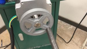
The next part of the project was getting the barrel threaded. Some time ago I made a .30 caliber suppressor, on a Form 1, and it was designed so that I can make a wide variety of adaptor mounts to fit it across, well, any firearm that fires a .30 projectile or smaller! The barrel had just barely enough meat to be threaded 9/16-24 and have a shoulder for the suppressor adaptor to tighten against, and there was just enough stick out in front of the magazine tube and front sight. It was like serendipity! At the time I was threading this, the lathe I had was a Grizzly Mini Lathe, 7×14″. A very small machine for this sort of operation to be sure, this remains as the largest project I’ve done on that little lathe and I’ll be honest, I was pushing it! I could fit the barrel of the rifle through the spindle of the headstock, since I was just working on the first .600″ of the muzzle anyway, but I needed to open up the spindle bore just a hair with a 13/16″ drill bit. This will probably void your warranty! Opening up the spindle bore gave me just enough space to get the barrel into the headstock so I could work on the muzzle. The rest of the story is relatively straight forward; I threaded the barrel using the single point method on the lathe and we got a perfect fitting 9/16-24 thread!
With the barrel threaded I made an adaptor for the 9/16-24 threads on the barrel to fit the angled shoulder and larger, custom threads that are in my .30 Suppressor.
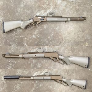
The last big part of the process is a complete refinish of the metal! Using 80 grit Aluminum Oxide in a media blasting cabinet the surface of all the metal was brought down to bare and a perfectly smooth satin. This was done to the barrel, receiver, magazine tube, lever, and a couple other small parts. I also blasted an XS Sight Systems scout rail, another upgrade I thought was key in this rifle! The media blasting is a necessary step in preparing the metal for Cerakote. Cerakote is a baked on epoxy style coating with impregnated ceramics. It’s extremely tough and not difficult to apply in the home shop, in my experience. This, however, was once again the largest item I’d done and it was a little tricky. I could fit the rifle and mag tube and all the other parts in my kitchen’s oven (this process isn’t very aromatic and the smell quickly vacates…..plus it was a rental) but the distance to travel between where I was spraying and where the oven was, made the transfer a bit on the scary side. With some help getting everything from my “spray booth” to the kitchen’s oven, I managed to not smudge any of the cerakote before the baking process! 2 hours later, it was done and the rifle could be reassembled!
I’m very proud of how it all came out, and it ended up absolutely beautiful in my opinion! The color of Cerakote I used is called “Burnt Bronze” and it’s my new favorite.
I also loaded up some subsonic .30-30 loads using the powder “Trail Boss” which is superb for getting slow speeds!
With subsonic ammunition, the rifle is extremely quiet. It took a few months (moving interruption) before I could give it a full test fire, but comparing it to other firearms, with subsonic ammo, it’s about as loud as a .22 pistol with a suppressor. Yeah.
It’s an absolute joy to shoot, and I may go back “in” and do some more polishing and fine tuning of the action; it still has some parts that could be smoother.
If you’ve read this far, thank you for visiting my page! Patreon members who support me for as little as $1 per month get to see my videos early, as well as get access to monthly update VLogs, and in this case, patrons got to see the test fire video before anyone else!
Thank you for stopping by to the new internet home of Practical Renaissance, the story of just a regular guy in his shop making things out of metal, wood, and anything else that’s neat, and sharing it with you all! Please forgive the sparseness as I get everything filled out to make the best possible experience for you!